
Instruction Manual for Elliptical Gear Flow Meter
Release time:
2014-08-29
I. Applications:
Oval gear flow meters are lightweight volumetric flow meters with a pointer display, a digital counter, and a zeroing device. They are widely used for liquid flow control in various industrial fields and are suitable for measuring various types of liquids, such as crude oil, diesel, and gasoline. They feature a large measuring range, high accuracy, and easy operation and maintenance. By selecting different manufacturing materials, they can meet the liquid flow measurement needs of various fields, including petroleum, chemical, pharmaceutical, food, metallurgical, power, and transportation industries.
II. Working Principle and Structure:
The flow meter consists of a measuring chamber and a pair of oval gears inside the chamber. Together with the upper and lower cover plates, they form a sealed crescent-shaped cavity (not completely sealed due to gear rotation), which serves as the unit for calculating the single displacement volume. When the liquid to be measured enters the flow meter through the pipeline, the pressure difference generated at the inlet and outlet drives the pair of gears to rotate continuously, constantly delivering the liquid measured by the crescent-shaped cavity to the outlet. The product of the number of revolutions of the oval gears and four times the single displacement volume is the total volume of the measured liquid (see Figure 1 for the principle).
The flow meter mainly consists of a housing, a counter, oval gears, and a coupling (magnetic coupling or axial coupling) (see Figure 2 for the structure).
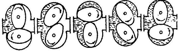
Figure 1 Diagram of Oval Gear Operation Principle
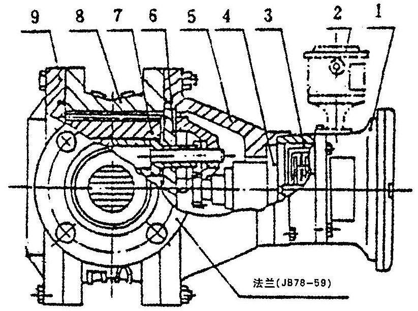
(Figure 2) Structural Diagram of Oval Gear Flow Meter
1. Counter 2. Transmitter 3. Precision Adjuster (Used for DN50 and above)
4. Sealed Coupling 5. Front Cover 6. Cover Plate 7. Oval Gear
8. Housing 9. Rear Cover
III. Technical Data:
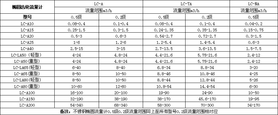
Oval Gear Flow Meter Dimensions
(1) Dimensions of Cast Iron, High Viscosity Cast Iron, High Temperature Cast Iron, and Deformed Cast Iron Oval Gear Flow Meters
Unit:mm
| Nominal Diameter |
L |
H |
A |
B |
D |
D1 |
N(pcs) |
Φ |
| 10 |
150 |
100 |
165 |
210 |
90 |
60 |
4 |
14 |
| 15 |
170 |
118 |
172 |
226 |
95 |
65 |
4 |
14 |
| 20 |
200 |
150 |
225 |
238 |
105 |
75 |
4 |
14 |
| 25 |
260 |
180 |
232 |
246 |
115 |
85 |
4 |
14 |
| 40 |
245 |
180 |
249 |
271 |
145 |
110 |
4 |
18 |
| 50 |
340 |
250 |
230 |
372 |
160 |
125 |
4 |
18 |
| 65 |
420 |
325 |
270 |
386 |
180 |
145 |
4 |
18 |
| 80 |
420 |
325 |
315 |
433 |
195 |
160 |
8 |
18 |
| 100 |
515 |
418 |
370 |
458 |
215 |
180 |
8 |
18 |
| 150 |
540 |
515 |
347 |
557 |
280 |
240 |
8 |
23 |
| 200 |
650 |
650 |
476 |
720 |
335 |
295 |
12 |
Recent News


Address: No.32, Hetang Road, Luyang Economic Development Zone, Hefei City, Anhui Province
Telephone: 0086-551-65661688/65663688
Fax: 0086-551-65661780
E-mail: ceo@ahtwyb.cn

Follow Us

Tianwei TikTok
Copyright©2025 Anhui Tianwei Instrument Co., Ltd. All Rights Reserved.