
Waist wheel flow meter instructions
Release time:
2014-08-29
1 Overview
Oval gear flow meters are high-precision metering instruments used for continuous or intermittent measurement of flow rate in pipelines. They are characterized by high accuracy, good reliability, light weight, long life, and easy installation and use, which are typical characteristics of volumetric flow meters.
Oval gear flow meters mainly consist of three parts: a metering chamber, a sealed coupling, and a counter. They can indicate accumulated flow and instantaneous flow on-site, and with a transmitter and flow intelligent controller, they can realize remote measurement and control. They are widely used in petroleum, chemical, power, metallurgy, transportation, food processing, medicine, national defense, and commercial trade sectors for the precise measurement of petroleum and petroleum products, chemical solutions, and other fluids.
■ 2. Working Principle
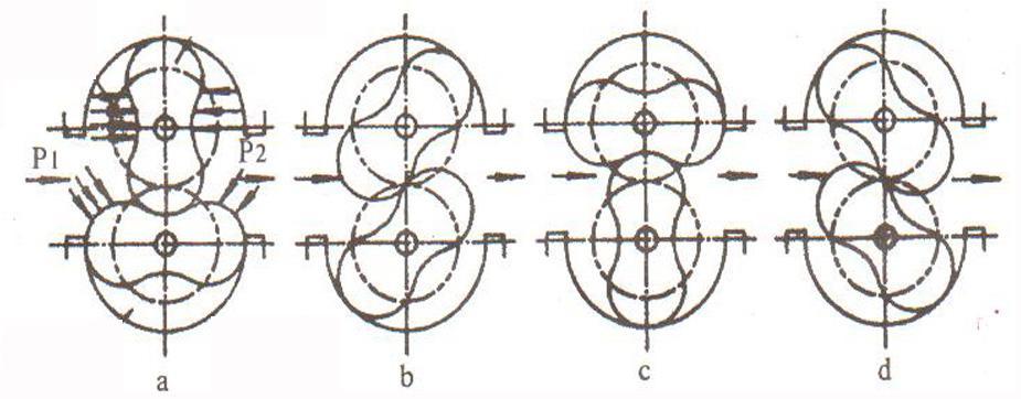
When the liquid to be measured flows through the metering chamber, a pressure difference is formed at the inlet and outlet of the flow meter, and the oval gear rotates under the driving force of this pressure difference. At the same time, a pair of drive gears fixed on the oval gear shaft keeps the two oval gears continuously rotating. As the oval gear rotates, the liquid is continuously discharged from the flow meter through the metering chamber. The amount of liquid passing through each pair is four times the volume of the metering chamber. Through the sealed coupling and deceleration mechanism, the number of rotations is decelerated and then transmitted to the counter, which indicates the instantaneous and accumulated flow rate of the liquid.
Installing a transmitter in the counter mechanism forms an oval gear flow meter with a transmitter. Paired with a display instrument or microcomputer system, it can realize remote (quantitative, cumulative, instantaneous, etc.) automated measurement and control. For instructions, please refer to the display instrument classification manual.
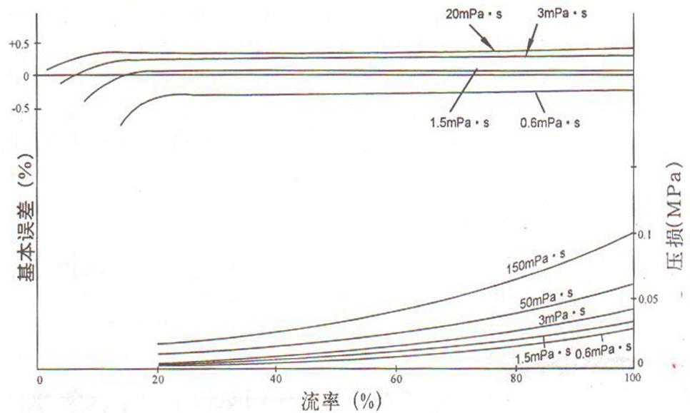
3. Performance and Pressure Loss Curve
■ 4. Technical Parameters
① Nominal pressure (MPa): 0.6, 1.0, 1.6, 2.5, 4.0
② Operating temperature (°C): -10~60
③ Accuracy grade: 0.5, 0.2
④ Flow range (m3/h)
Nominal Diameter (mm) | Liquid Viscosity 2.0~150mpa.s | Liquid Viscosity 0.6~2.0mpa.s | Liquid Viscosity 2.0~150mpa.s | Liquid Viscosity 0.6~2.0mpa.s |
15 | 0.3~3 | 0.6~3 | 0.8~3 | 1~3 |
25 | 0.6~6 | 1.2~6 | 1.5~6 | 2~6 |
40 | 1.6~16 | 3.2~16 | 4~16 | 5~16 |
50 | 2.5~25 | 5~25 | 6~25 | 8~25 |
65 | 6~50 | 12~50 | 15~50 | 20~50 |
80 | 6~60 | 12~60 | 15~60 | 20~60 |
100 | 10~100 | 20~100 | 25~100 | 33~100 |
150 | 25~250 | 50~250 | 60~250 | 80~250 |
Accuracy Class | 0.5 | 0.2 | ||
■ 5. Installation and Use of Oval Gear Flow Meters
(1) A filter should be installed before the flow meter, and the arrows on the bodies of both should point in the same direction as the flow.
(2) When the liquid being measured contains gas, a gas separator should be installed before the flow meter.
(3) Regardless of whether the pipeline is installed vertically or horizontally, the oval gear shaft of the flow meter should be installed horizontally (i.e., the dial should be perpendicular to the ground).
(4) If the reading is difficult to see under correct installation, the counter can be rotated 180 degrees or 90 degrees.
(5) The throttle valve should be installed at the inlet of the flow meter, and the shut-off valve should be installed at the outlet. When using the shut-off valve, start slowly and do not suddenly open the valve.
(6) It is strictly forbidden to use scouring steam through the flow meter.
(7) In continuous use departments, the flow meter needs to be equipped with a bypass pipe.
(8) Before installing the flow meter, the pipeline needs to be flushed. When flushing, use a straight pipe section (to replace the flow meter position) to prevent welding slag, debris, etc., from entering the flow meter.
(9) Do not use water to calibrate flow meters made of cast iron or cast steel.
(10) When using the flow meter, the flow rate must not exceed the technical requirements. The optimal operating range of the flow meter is 70% to 80% of the maximum flow rate.
(11) If the liquid to be measured is chemically corrosive, a stainless steel flow meter should be selected. If the corrosiveness is strong, a 0Crl8Ni12MO2Ti material flow meter should be selected.
Recent News

Address: No.32, Hetang Road, Luyang Economic Development Zone, Hefei City, Anhui Province
Telephone: 0086-551-65661688/65663688
Fax: 0086-551-65661780
E-mail: ceo@ahtwyb.cn

Follow Us

Tianwei TikTok
Copyright©2025 Anhui Tianwei Instrument Co., Ltd. All Rights Reserved.