
Rotary flowmeter instruction manual
Release time:
2014-08-29
I. Overview
Applications
The rotary vane flow meter (hereinafter referred to as flow meter) is a precision instrument used for measuring and controlling the flow rate of liquids in pipelines. Flow meters can be manufactured from different materials and are widely used in petroleum, chemical, light industry, commerce, and scientific research departments. They are particularly suitable for metering crude oil, refined oil, and light hydrocarbons, and are currently the latest generation of positive displacement flow meters in China.
The flow meter is equipped with a pointer, a numerical counter, and can indicate the accumulated flow rate. The counter with a zero reset device can also indicate the single accumulated quantity, and can output electrical pulse signals for secondary instruments or computer detection, automatic control and data processing, etc.
Features
1. High measurement accuracy, wide flow range, and good repeatability.
2. The rotary vane rotates uniformly, with little vibration, and a long lifespan.
3. Insensitive to changes in the viscosity of the measured liquid.
4. Simple structure, small size, and light weight.
5. Easy installation.
II. Working Principle and Structure
Working Principle
This flow meter is a positive displacement flow meter. It uses the empty slot part of the rotary vane (measuring element) and the inner wall of the measuring chamber to form a closed cavity (see the shaded area in the figure) as the measuring chamber. Each rotation of the rotor outputs 8 times the volume of the cavity. Therefore, the flow rate of the fluid is proportional to the rotational speed of the rotor. The accumulated number of rotor rotations is converted into the measurement of fluid flow (see Figure 1).
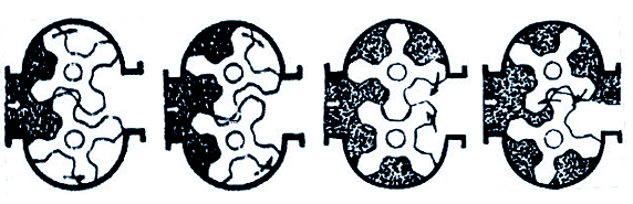
Figure 1 Rotary Vane Operating PrincipleStructure
The flow meter is mainly composed of the main body, a pair of rotary vanes, a magnetic coupling, a deceleration mechanism, an adjusting gear, a counter, and a signal transmission device.
The number of rotations of the rotary vane is transmitted to the head counter through a magnetic coupling and a deceleration mechanism composed of a series of gears. The magnetic coupling is mainly composed of an active magnet and a driven magnet. The use of a magnetic coupling can improve the working pressure and working temperature of the flow meter, ensuring safe operation and reducing maintenance work.
III. Technical Characteristics
Main Technical Performance
1. Nominal diameter: 25, 40, 50, 80, 100, 150, 200, 250, 300.
2. Allowable basic error (%): ±0.2, ±0.5.
3. Repeatability error (%): 0.2 grade is 0.07, 0.5 grade is 0.17 (0.5 grade).
4. Allowable working pressure (Mpa): 1.6, 2.5, 4, 6.4.
5. Measured medium temperature (°C): -40~+60, -40~+120, 100~300.
6. Measured medium viscosity (Mpa·s): 0.6~200.
7. Explosion-proof grade: dⅡBT4, iaIICT4 (Note: This factory's signal remote transmission flow meters are divided into ordinary and explosion-proof types).
8. Pipeline flange standard: HG20592-90, JB/T79.1-94.
9. Main materials of the flow meter: stainless steel, cast steel, 316 (i.e., 0Cr17Ni12Mo2 stainless steel bearings for gasoline medium, high-temperature bearings for high-temperature medium).
Specifications and Flow Range
The flow range of the flow meter (0.5 grade flow meter) is shown in the table below
Nominal Diameter (mm) | Flow Range (m³/h) | ||
0.6~2mpa·s | 2~8mpa·s | 8~200mpa·s | |
25 | 1.5~10 | 1~10 | 1~10 |
40 | 3~22 | 2.5~25 | 2.5~25 |
50 | 4.5~36 | 9~36 | 9~36 |
80 | 10~100 | 15~100 | 20~100 |
100 | 13~135 | 15~150 | 25~150 |
150 | 28~225 | 25~250 | 55~250 |
200 | 42~342 | 38~380 | 90~380 |
250 | 70~550 | 60~600 | 130~450 |
300 | 110~880 | 100~1000 | 220~700 |
If the accuracy of the flow meter is 0.2 grade, the lower limit of the flow rate is obtained by multiplying the lower limit in Table 1 by 2. When the temperature of the measured medium is +100~300℃, the maximum flow rate is obtained by multiplying the coefficient 0.8.
Recent News



Address: No.32, Hetang Road, Luyang Economic Development Zone, Hefei City, Anhui Province
Telephone: 0086-551-65661688/65663688
Fax: 0086-551-65661780
E-mail: ceo@ahtwyb.cn

Follow Us

Tianwei TikTok
Copyright©2025 Anhui Tianwei Instrument Co., Ltd. All Rights Reserved.