
Vortex Flow Meter Instruction Manual
Release time:
2014-08-29
I. Overview
Vortex flow meters are velocity-type flow instruments made using the natural vibration principle of fluids based on the Karman vortex street theory, with piezoelectric crystals or differential capacitance as detection components.
This instrument uses advanced differential technology, along with isolation, shielding, and filtering measures, to overcome problems such as poor shock resistance and disordered small signal data in similar products. It also employs unique sensor packaging technology and protective measures to ensure product reliability. The product comes in basic and composite types; the basic type measures a single flow signal, while the composite type can simultaneously measure temperature, pressure, and flow. Each type has integral and split structures to adapt to different installation environments.
This instrument has a series of advantages, including a wide measurement range, high accuracy, convenient installation and maintenance, and broad media adaptability. It can be widely used in various low-viscosity liquid, gas, and steam single-phase flow process measurement and energy-saving management in industries such as petrochemicals, metallurgy, machinery, food, papermaking, and urban pipeline heating, water supply, and gas supply.
II. Working Principle
A vortex flow meter consists of a vortex shedding body designed in the flow field, a detection probe, and corresponding electronic circuits. When fluid flows through the vortex shedding body, two alternating rows of vortices are formed on both sides; these vortices are known as Karman vortex streets. Based on the Karman vortex street theory, Strouhal further proposed that the frequency of the Karman vortex street is proportional to the flow velocity of the fluid and gave the relationship between frequency and velocity:
f = St × V/d
Where: f Vortex shedding frequency (Hz)
V Average flow velocity on both sides of the vortex shedding body (m/s)
St Strouhal number (constant)
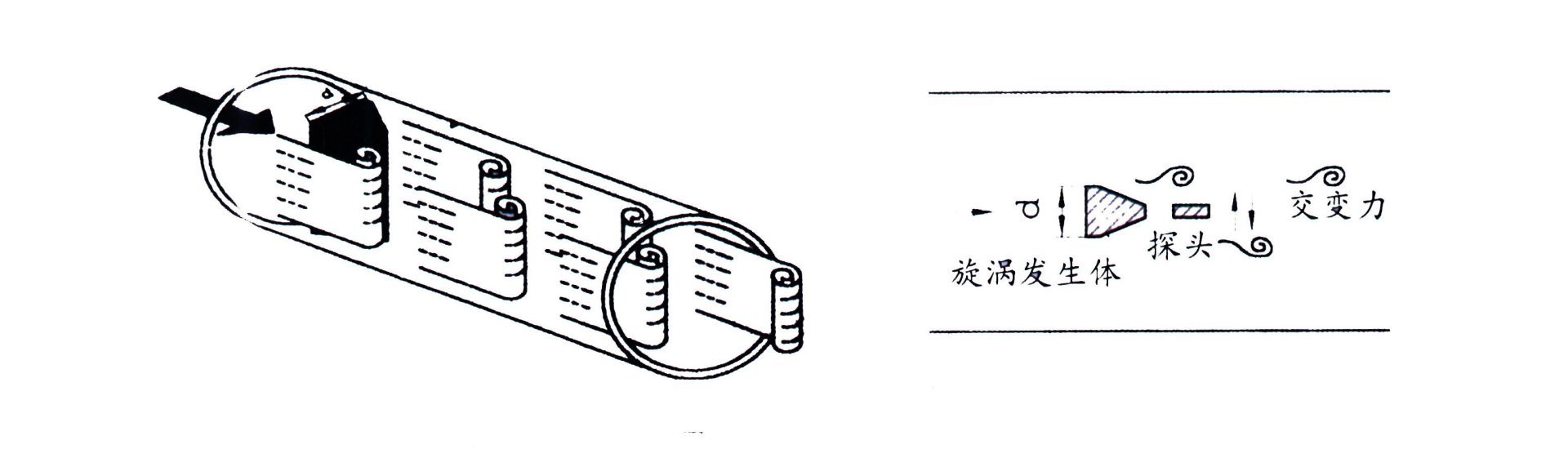
Figure 1
These alternating vortices form a series of alternating negative pressures. This pressure acts on the detection probe, generating a series of alternating electrical signals. After pre-amplification, shaping, and amplification, a pulse frequency signal (or standard signal) proportional to the vortex is output.
III. Basic Characteristics
● Easy installation and maintenance.
● Simple and robust structure, no moving parts, highly reliable long-term operation.
● Wide measurement range, turndown ratio up to 1:10.
● Low pressure loss, low operating costs, and more energy-efficient.
● Wide range of applications, measurable for liquids, gases, and steam.
● Long calibration cycle, generally two years.
● Within a certain Reynolds number range, the output signal is not affected by the physical properties and component changes of the measured medium. The instrument coefficient is only related to the shape and size of the vortex shedding body. After replacing the accessories, the instrument coefficient generally does not need to be recalibrated.
● The output is a pulse signal proportional to the flow rate, with no zero drift and high accuracy.
● The detection probe does not directly contact the measured medium, resulting in more stable performance.
IV. Technical Parameters
● Measured medium: Liquid, gas, steam
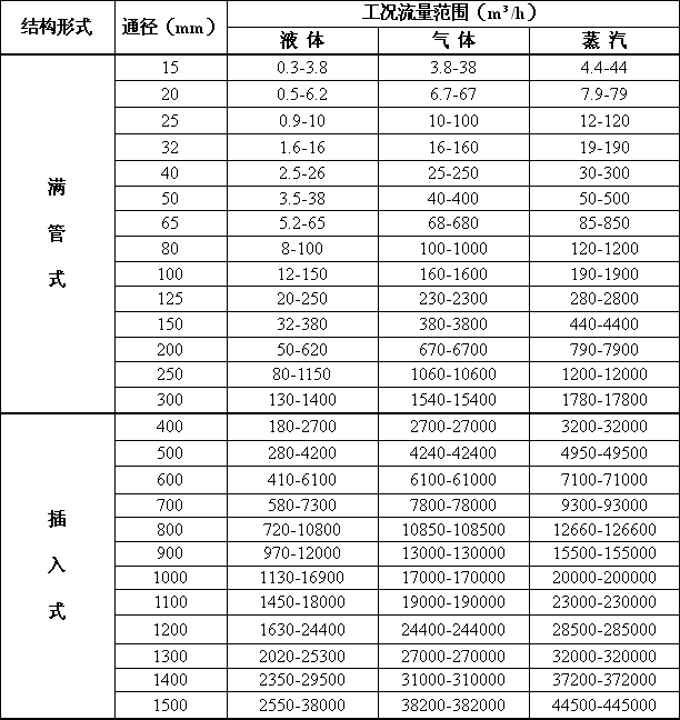
● Measurement range: (See Table 1)
● Nominal diameter: 25-1500mm Non-standard products can be customized according to user requirements
● Temperature range: Piezoelectric -40℃ ~ 350℃ Capacitive -60℃ ~ 500℃
● Pressure rating: PN1.6Mpa; PN2.5Mpa; PN4.0Mpa, higher pressure ratings can be customized
● Turndown ratio: Normal range 1:10 Extended range 1:15
● Pressure loss coefficient: Cd≤2.6
● System measurement accuracy: Liquid, gas ±1% of indicated value
Steam ±1.5% of indicated value
Insertion flow meter ±2.5% of indicated value
● Supply voltage: Sensor +12VDC, +24VDC (optional) Transmitter +24VDC
On-site display type Instrument with built-in 3.6V lithium battery
● Output signal: Sensor Pulse frequency signal 0.1 ~ 3000Hz Low level ≤1V High level ≥6V
Transmitter Two-wire 4 ~ 20mA.DC current signal
● Allowable vibration acceleration: Piezoelectric ≤0.2g Capacitive ≤1.0g
● Ambient temperature: Sensor: -30℃ ~ 65℃ Transmitter, on-site display: -10℃ ~ 50℃
● Ambient humidity: Relative humidity 5 ~ 85%
● Atmospheric pressure: 86 ~ 106Kpa
● Signal transmission distance: ≤500m
● Signal cable interface: Internal thread M20×1.5
● Explosion-proof grade: (ia)ⅡCT2 — T5
● Protection grade: Ordinary type IP65 Submersible type IP68
● Instrument material: The instrument housing is made of aluminum alloy, and the body part is made of stainless steel 304 material. Special materials can also be used according to user requirements.
Recent News



Address: No.32, Hetang Road, Luyang Economic Development Zone, Hefei City, Anhui Province
Telephone: 0086-551-65661688/65663688
Fax: 0086-551-65661780
E-mail: ceo@ahtwyb.cn

Follow Us

Tianwei TikTok
Copyright©2025 Anhui Tianwei Instrument Co., Ltd. All Rights Reserved.